


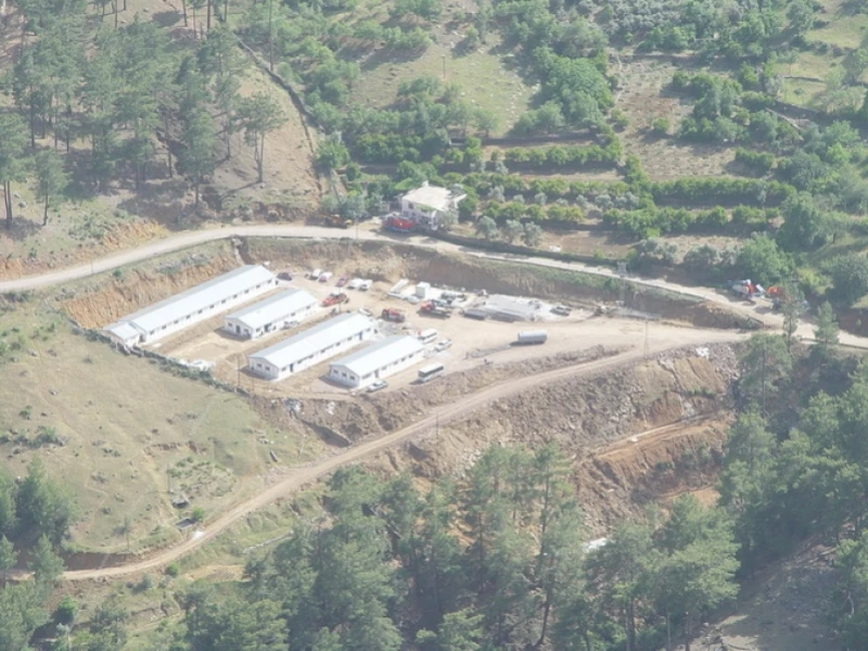
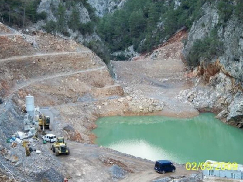


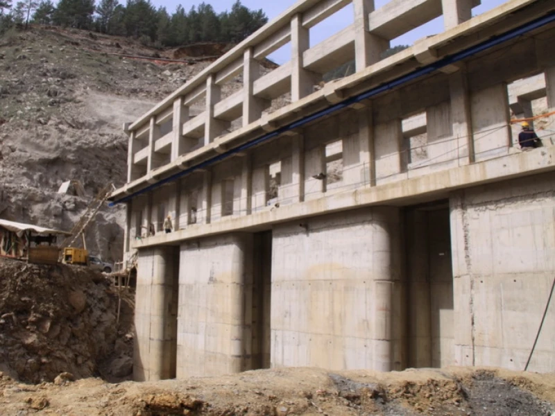


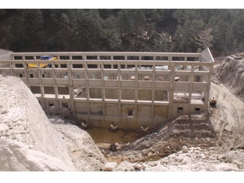
The Otluca Hydroelectric Power Plant (HPP) Project is located in the Mediterranean Region of Türkiye, within the boundaries of Anamur District, İçel (Mersin) Province, on the main branch of Anamur River and its tributary, Boğuntu Stream. The project site is approximately 20 km north of Anamur District.
The structures within the scope of the project consist of the following systems and components:
The Otluca I HPP system consists of the Otluca I Regulator on Anamur River at 372.50 m thalweg and 383.50 m crest elevation, approximately 3,890 m long Energy Tunnel-1, a 500 m long Transmission Channel, a 2,210 m long Energy Tunnel-2, the Otluca I head pond, penstock, and the Otluca I powerhouse building.
The Otluca II HPP system consists of the gated Otluca II Regulator on Anamur River at 156.50 m thalweg, 159.00 m crest, and 165.00 m normal water level, approximately 451 m long Energy Tunnel-1, a 59 m long Transmission Channel-1, a 680 m long Energy Tunnel-2, a 350 m long Transmission Channel-2, the Otluca II head pond, penstock, and the Otluca II powerhouse building.
The Boğuntu HPP system consists of the Boğuntu Regulator on Boğuntu Stream at 228.00 m thalweg and 233.50 m crest elevation, approximately 162 m long Transmission Channel, a 1,365 m long Energy Tunnel, the Boğuntu head pond, penstock, and the Boğuntu powerhouse building.
In all three systems, stream water is diverted through the intake structures of the regulators. The intake structures include trash racks and operation/cofferdam gates. After passing through the gated section, the water enters the settling basin. At the outlet of the settling basin, operation gates are provided. By closing the inlet and outlet gates, the basin can be flushed using the flushing gates located at the lower elevation of the settling basin.
After the settling basin, the water is conveyed to the head ponds via the transmission system (channel + tunnel) specific to each system. In the head pond, after the trash rack, a water intake structure and valve chamber are provided for the penstock. From this point onward, the water is conveyed to the turbines in the powerhouse via the penstock.
| Design Discharge | 20.00 m3/s |
|---|---|
| Number of Units | 3 units |
| Installed Capacity | 35.62 MW |
| Gross Head | 213.36 m |
| Design Discharge | 24.00 m3/s |
|---|---|
| Number of Units | 3 units |
| Installed Capacity | 35.62 MW |
| Gross Head | 39.41 m |
| Design Discharge | 15.00 m3/s |
|---|---|
| Number of Units | 3 units |
| Installed Capacity | 3.36 MW |
| Gross Head | 69.70 m |
© 1986-2026 Doğru Engineering | All rights reserved.
Developed by: Idesa Creative